| Sign In | Join Free | My esadidasol.com |
|
| Sign In | Join Free | My esadidasol.com |
|
| Categories | Outdoor Disconnector Switch |
|---|---|
| Brand Name: | HengAnshun |
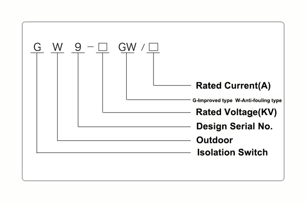
| Model Number: | GW9-10/630 |
| Place of Origin: | China |
| MOQ: | 1 set |
| Price: | USD159/Unit Based on EXW |
| Supply Ability: | 10000 units/month |
| Delivery Time: | 10 work days |
| Packaging Details: | Export wooden case packing |
| Color: | Gray |
| Current: | 630A~1250A |
| Voltage: | 12kV~36kV |
| Quality: | High |
| Keyword: | Outdoor Disconnector Switch |
| Application: | Outdoor distribution |
Durable Outdoor Disconnector Switch Portable And Easy Installation For High Voltage Powerful Electrical Substation
Product Description:
Outdoor disconnector switches play a crucial role in high-voltage
power transmission and distribution systems. They are specifically
designed to disconnect circuits from their power sources for
maintenance or repair purposes, ensuring the safety of workers
performing tasks on the system.
The primary function of an outdoor disconnector switch is to
isolate the circuit from the power supply. This is achieved through
a rotating pole that controls the opening and closing of the
switch's blade or contact. By rotating the pole, the blade can be
engaged or disengaged, effectively connecting or disconnecting the
circuit. This manual operation provides a visible indication of the
switch's status, allowing operators to easily determine whether the
circuit is energized or de-energized.
Operator safety is of paramount importance when dealing with
high-voltage systems. Therefore, the pole of an outdoor
disconnector switch is typically constructed of a non-conductive
material, such as fiberglass or composite materials. This choice of
materials ensures that the pole provides insulation against the
high voltage present in the system, protecting the operator from
electric shock during switch operation.
Outdoor disconnector switches are available in different designs
and sizes to accommodate the voltage and current ratings of the
circuits they control. They are commonly installed on poles or
structures in outdoor settings for easy accessibility and
operation. When used in conjunction with other protective devices
like circuit breakers and fuses, disconnector switches contribute
to the overall safety and reliability of the electrical system by
providing a means of isolation and protection.
Feature:
1.Isolation and Maintenance: Outdoor disconnector switches provide
a means of isolating circuits from their power sources during
maintenance or repair activities. This isolation ensures that
workers can safely work on the system without the risk of electric
shock. By disconnecting the circuit, the switch allows for the
de-energization of specific sections, enabling maintenance tasks to
be performed safely.
2.Visible Indication: The manual operation and visible indication
of the switch's status enhance safety. Operators can easily
determine whether the circuit is connected or disconnected by
observing the position of the switch's blade or contact. This
visual indication helps prevent accidental contact with live
circuits, reducing the risk of electrical accidents.
3.Protection from Electrical Hazards: The non-conductive pole
material used in outdoor disconnector switches provides insulation
against the high voltage present in the system. This insulation
protects the operator from electric shock during switch operation.
It acts as a barrier between the operator and the live electrical
components, minimizing the risk of injuries.
4.Coordination with Protective Devices: Outdoor disconnector
switches work in conjunction with other protective devices, such as
circuit breakers and fuses. These devices complement each other to
ensure the overall safety and reliability of the electrical system.
Disconnector switches can be used to isolate faulty sections of the
system, allowing circuit breakers or fuses to trip and protect the
system from further damage.
5.Accessibility and Reliability: Outdoor disconnector switches are
designed to be easily accessible and operable. They are typically
installed on poles or structures in outdoor settings, allowing
quick and convenient access for maintenance personnel. Their robust
construction and reliable operation contribute to the overall
reliability of the electrical system, minimizing downtime and
ensuring uninterrupted power supply.
Operation
1.Initial Position: The disconnector switch is initially in the closed position, meaning the circuit is connected and energized. The switch's blade or contact is in contact with the corresponding terminals or conductors, allowing the flow of electrical current.
2.Preparation and Safety Measures: Before operating the switch, proper safety measures should be taken, such as wearing appropriate personal protective equipment (PPE) and ensuring the area is clear of any potential hazards. It is essential to follow established safety protocols and guidelines.
3.Manual Operation: The operator rotates the switch's pole or handle, which controls the opening and closing of the switch's blade or contact. The pole is typically located at a safe distance from the live electrical components and is made of a non-conductive material for insulation.
4.Opening the Switch: By rotating the pole, the switch's blade or contact is disengaged from the terminals or conductors, effectively opening the circuit. This action interrupts the flow of electrical current and disconnects the circuit from its power source.
5.Visible Indication: As the switch is operated, it provides a visible indication of its status. The position of the switch's blade or contact can be observed, usually through a transparent enclosure or by using visual indicators, to determine whether the circuit is connected or disconnected.
6.Maintenance or Repair: With the disconnector switch in the open position, maintenance or repair activities can be safely performed on the circuit. Workers can work on the system without the risk of electric shock, as the circuit is isolated from the power source.
7.Closing the Switch: Once the maintenance or repair tasks are completed, and it is safe to restore power to the circuit, the operator rotates the pole in the opposite direction to close the switch. The blade or contact re-engages with the terminals or conductors, reconnecting the circuit to its power source.
8.Verification: After closing the switch, it is important to verify that the circuit has been successfully re-energized and is functioning correctly. This can be done through appropriate testing and monitoring procedures to ensure the system is operating as intended.
Application:
1.Maintenance and Repair: The Loadbuster Electrical Isolator is commonly used to isolate and ground electrical distribution lines for maintenance and repair activities. It allows maintenance personnel to work safely on energized equipment without the risk of electrocution.
2.Emergency Response: The Loadbuster Electrical Isolator can be used in emergency situations, such as power outages or natural disasters, to isolate and ground electrical distribution lines and restore power safely.
3.Switching Operations: The Loadbuster Electrical Isolator can be used to open or close switches and perform other switching operations on electrical distribution lines.
Condition:
1.The maximum altitude for installation should not exceed 1000m.
2.The ambient air temperature should not exceed +40'C, and in general areas, it should not fall below -30'C. In Paramos areas, it should not fall below -40'C.
3.The wind pressure should not exceed 700Pa, corresponding to a wind speed of 34m/s.
4.The isolator should be able to withstand earthquakes of up to 8 degrees in intensity.
5.The isolator should be installed in a location where there is no frequent violent vibration.
6.For ordinary type isolators, they should be kept away from gas, smoke, chemical deposition, salt-spray fog, dust, and other explosive and corrosive materials that can seriously affect the isolator's insulation and conduction capability.
7.Pollution-proof type isolators are suitable for use in severely filthy conduction areas, but they should not be installed in areas with any explosive or fire-causing materials.
Technical Parameters:
| Serial No. | Parameter | Unit | Data | |||||||||
| 1 | Rated Voltage | kV | 12 | |||||||||
| 2 | Rated Current | Model No. | (H)GW9-12(W)/630-20 | A | 630 | |||||||
| (H)GW9-12(W)/1000-20 | 1000 | |||||||||||
| (H)GW9-12(W)/1250-31.5 | 1250 | |||||||||||
| 3 | 4s Short-time withstanding current | Model No. | (H)GW9-12(W)/630-20 | kA | 50 | |||||||
| (H)GW9-12(W)/1000-20 | 50 | |||||||||||
| (H)GW9-12(W)/1250-31.5 | 80 | |||||||||||
| 4 | Rated Insulation Level | Lightning surge withstand voltage(peak) | Polar-to-Earth (Positive & Negative) | kV | 75 | |||||||
| Interfracture (Positive & Negative) | 85 | |||||||||||
| Industrial frequency withstand voltage (1 min) (Effective value) | Dry Test/Wet Test | Polar-to-Earth | 42(Dry) 34(Wet) | |||||||||
| Interfracture | 48(Dry) | |||||||||||
| 48(Dry) | ||||||||||||
| 48(Dry) 40(Wet) | ||||||||||||
| 5 | Main Circuit Resistance | μ Ω | 630 | |||||||||
| 1000 | ||||||||||||
| 1250 | ||||||||||||
| 6 | Mechanical Life Time | times | 50 | |||||||||
| 50 | ||||||||||||
| 80 | ||||||||||||


|
