| Sign In | Join Free | My esadidasol.com |
|
| Sign In | Join Free | My esadidasol.com |
|
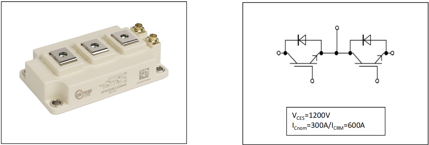
Solid Power-DS-SPS300B12G6M4-S04020025
1200V 300A IGBT Half Bridge Module
Features:
□ 1200V Trench+ Field Stop technology
□ Freewheeling diodes with fast and soft reverse recovery
□ VCE(sat) with positive temperature coefficient
□ Low switching losses
Typical Applications:
□ Inductive heating
□ Welding
□ High frequency switching application
![]()
Package
| Item | Symbol | Conditions | Values | Unit | |||
Isolation test voltage | VISOL | RMS, f = 50 Hz, t =1 min | 4.0 | kV | |||
Material of module baseplate | Cu | ||||||
Internal isolation | (class 1, IEC 61140) Basic insulation (class 1, IEC 61140) | Al2O3 | |||||
Creepage distance | dCreep | terminal to heatsink | 29.0 | mm | |||
| dCreep | terminal to terminal | 23.0 | |||||
Clearance | dClear | terminal to heatsink | 23.0 | mm | |||
| dClear | terminal to terminal | 11.0 | |||||
Comparative tracking index | CTI | >400 | |||||
| Item | Symbol | Conditions | Values | Unit | |||
| Min. | Typ. | Max. | |||||
Stray inductance module | LsCE | 20 | nH | ||||
Module lead resistance, terminals - chip | RCC’+EE’ | TC=25℃ | 0.70 | mΩ | |||
Storage temperature | Tstg | -40 | 125 | ℃ | |||
Mounting torque for module mounting | M6 | 3.0 | 6.0 | Nm | |||
Terminal connection torque | M6 | 2.5 | 5.0 | Nm | |||
Weight | G | 320 | g | ||||
![]()
IGBT
| Item | Symbol | Conditions | Values | Unit | |
Collector-emitter Voltage | VCES | Tvj=25℃ | 1200 | V | |
Maximum gate-emitter voltage | VGES | ±20 | V | ||
Transient gate-emitter voltage | VGES | tp≤10μs,D=0.01 | ±30 | V | |
Continuous DC collector current | IC | TC=25℃ | 400 | A | |
| TC=100℃ | 300 | ||||
Pulsed collector current,tp limited by Tjmax | ICpulse | 600 | A | ||
Power dissipation | Ptot | 1500 | W | ||
![]()
Characteristic Values
| Item | Symbol | Conditions | Values | Unit | |||
| Min. | Typ. | Max. | |||||
Collector-emitter saturation voltage | VCE(sat) | IC=300A, VGE=15V | Tvj=25℃ | 1.50 | 1.80 | V | |
| Tvj=125℃ | 1.65 | ||||||
| Tvj=150℃ | 1.70 | ||||||
Gate threshold voltage | VGE(th) | VCE=VGE, IC=12mA | 5.0 | 5.8 | 6.5 | V | |
Collector-emitter cut-off current | ICES | VCE=1200V, VGE=0V | Tvj=25℃ | 100 | µA | ||
| Tvj=150℃ | 5 | mA | |||||
Gate-emitter leakage current | IGES | VCE=0V,VGE=±20V, Tvj=25℃ | -200 | 200 | nA | ||
Gate Charge | QG | VCE=600V, IC=300A , VGE=±15V | 3.2 | μC | |||
Input Capacitance | Cies | VCE=25V, VGE=0V, f =100kHz | 60.0 | nF | |||
Output Capacitance | Coes | 1.89 | |||||
Reverse Transfer Capacitance | Cres | 0.54 | |||||
Internal gate resistor | RGint | Tvj=25℃ | 1.2 | Ω | |||
Turn-on delay time,inductive load | td(on) | VCC=600V,IC=300A RG=1.8Ω, VGE=±15V | Tvj=25℃ | 130 | ns | ||
| Tvj=125℃ | 145 | ns | |||||
| Tvj=150℃ | 145 | ns | |||||
Rise Time,inductive load | tr | Tvj=25℃ | 60 | ns | |||
| Tvj=125℃ | 68 | ns | |||||
| Tvj=150℃ | 68 | ns | |||||
Turn-off delay time,inductive load | td(off) | VCC=600V,IC=300A RG=1.8Ω, VGE=±15V | Tvj=25℃ | 504 | ns | ||
| Tvj=125℃ | 544 | ns | |||||
| Tvj=150℃ | 544 | ns | |||||
Fall time,inductive load | tf | Tvj=25℃ | 244 | ns | |||
| Tvj=125℃ | 365 | ns | |||||
| Tvj=150℃ | 370 | ns | |||||
Turn-on energy loss per pulse | Eon | VCC=600V,IC=300A RG=1.8Ω, VGE=±15V | Tvj=25℃ | 7.4 | mJ | ||
| Tvj=125℃ | 11.1 | mJ | |||||
| Tvj=150℃ | 11.6 | mJ | |||||
Turn off Energy loss per pulse | Eoff | Tvj=25℃ | 32.0 | mJ | |||
| Tvj=125℃ | 39.5 | mJ | |||||
| Tvj=150℃ | 41.2 | mJ | |||||
SC data | ISC | VGE≤15V, VCC=600V | tp≤10µs Tvj=150℃ | 1350 | A | ||
IGBT thermal resistance,junction-case | RthJC | 0.1 | K /W | ||||
Operating Temperature | TJop | -40 | 150 | ℃ | |||
![]()
Diode
| Item | Symbol | Conditions | Values | Unit | |
Repetitive reverse voltage | VRRM | Tvj=25℃ | 1200 | V | |
Continuous DC forward current | IF | 300 | A | ||
Diode pulsed current,tp limited by TJmax | IFpulse | 600 | |||
Characteristic Values
| Item | Symbol | Conditions | Values | Unit | |||
| Min. | Typ. | Max. | |||||
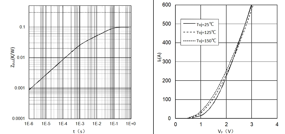
Forward voltage | VF | IF=300A , VGE=0V | Tvj=25℃ | 2.30 | 2.70 | V | |
| Tvj=125℃ | 2.50 | ||||||
| Tvj=150℃ | 2.50 | ||||||
Reverse recovery time | trr | IF=300A dIF/dt=-4900A/μs (Tvj=150°C) VR=600V, VGE=-15V | Tvj=25℃ | 90 | ns | ||
| Tvj=125℃ | 120 | ||||||
| Tvj=150℃ | 126 | ||||||
Peak reverse recovery current | IRRM | Tvj=25℃ | 212 | A | |||
| Tvj=125℃ | 245 | ||||||
| Tvj=150℃ | 250 | ||||||
Reverse recovery charge | QRR | Tvj=25℃ | 19 | µC | |||
| Tvj=125℃ | 27 | ||||||
| Tvj=150℃ | 35 | ||||||
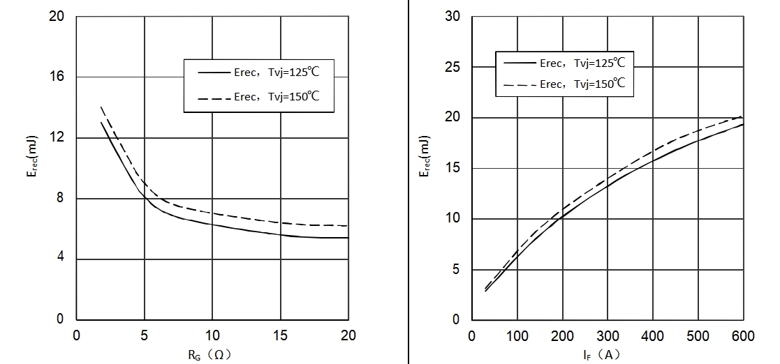
Reverse recovery energy loss per pulse | Erec | Tvj=25℃ | 7.7 | mJ | |||
| Tvj=125℃ | 13.3 | ||||||
| Tvj=150℃ | 14.0 | ||||||
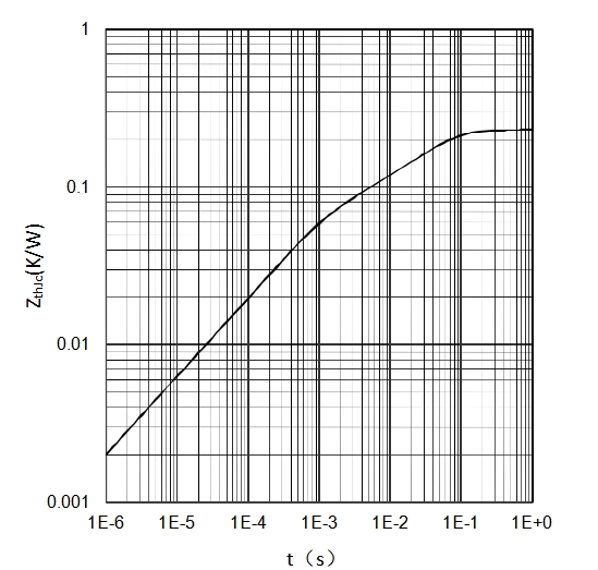
Diode thermal resistance,junction-case | RthJCD | 0.23 | K /W | ||||
Operating Temperature | TJop | -40 | 150 | ℃ | |||
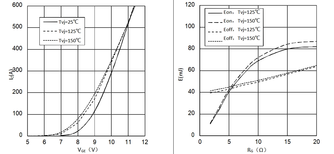
Output characteristic(typical) Output characteristic(typical)
IC = f (VCE) IC = f (VCE)
Tvj= 150°C
IGBT
Transfer characteristic(typical) Switching losses IGBT (typical)
IC = f (VGE) E = f (RG)
VCE = 20V VGE = ±15V, IC = 300A, VCE = 600V
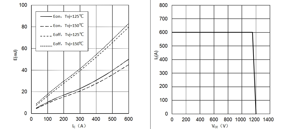
IGBT RBSOA
Switching losses IGBT (typical) Reverse bias safe operating area(RBSOA)
E = f (IC) IC =f (VCE)
VGE = ±15V, RG = 1.8Ω , VCE = 600V VGE = ±15V, RGoff = 1.8Ω, Tvj = 150°C
Typical capacitance as a function of collector-emitter voltage Gate charge (typical)
C = f (VCE) VGE = f (QG)
f = 100 kHz, VGE = 0V IC = 300A, VCE = 600V
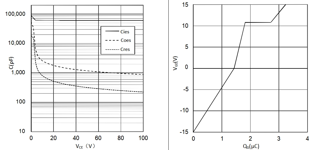
IGBT
IGBT transient thermal impedance as a function of pulse width Forward characteristic of Diode (typical)
Zth(j-c) = f (t) IF = f (VF)
![]()
Switching losses Diode(typical) Switching losses Diode(typical)
Erec = f (RG) Erec = f (IF)
IF = 300A, VCE = 600V RG = 1.8Ω, VCE = 600V
![]()
Diode transient thermal impedance as a function of pulse width
Zth(j-c) = f (t)
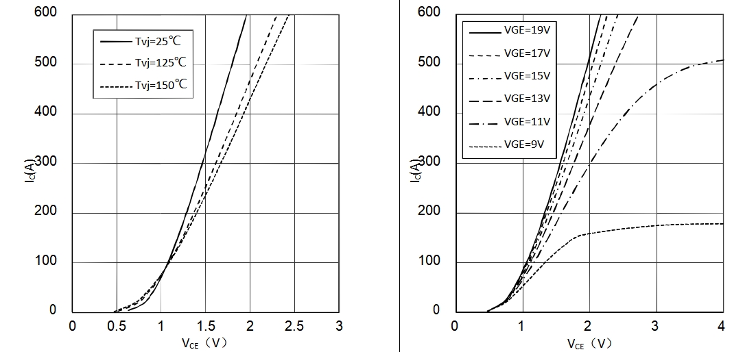
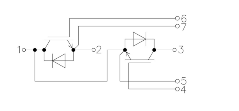
Circuit diagram headline
Package outlines
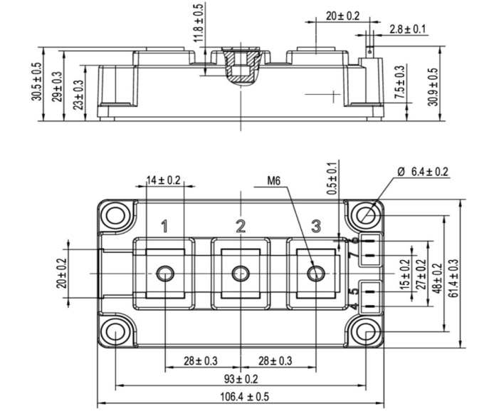
Dimensions in (mm)
mm

|
